The Circuits
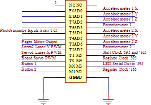
C32 Pin Out:
This project utilized a C32 microcontroller, with the pinout shown below. AD pins are analog to digital conversion pins. Port M and T pins are digital inputs or outputs, depending on the use.
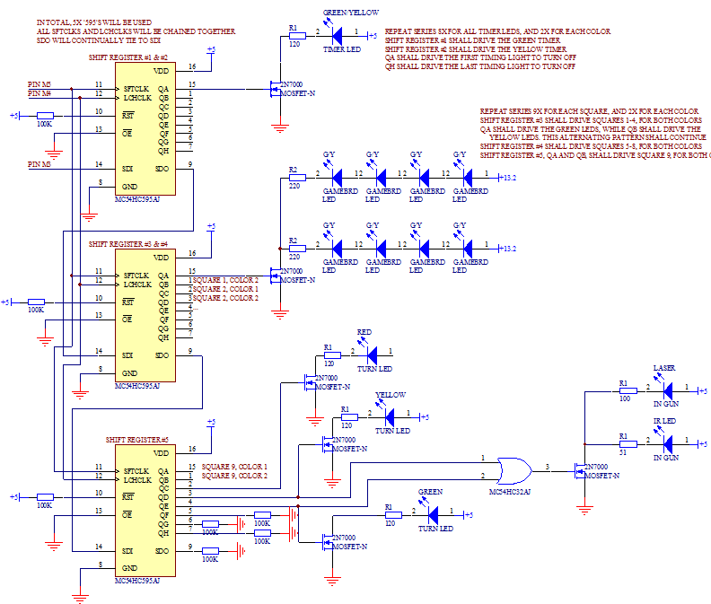
Output Shift Register Circuit for LEDs
Using a cascading series of output shift registers, we use 3 lines from the C32 to drive 37 unique outputs, controlling an astounding 164 LEDs.
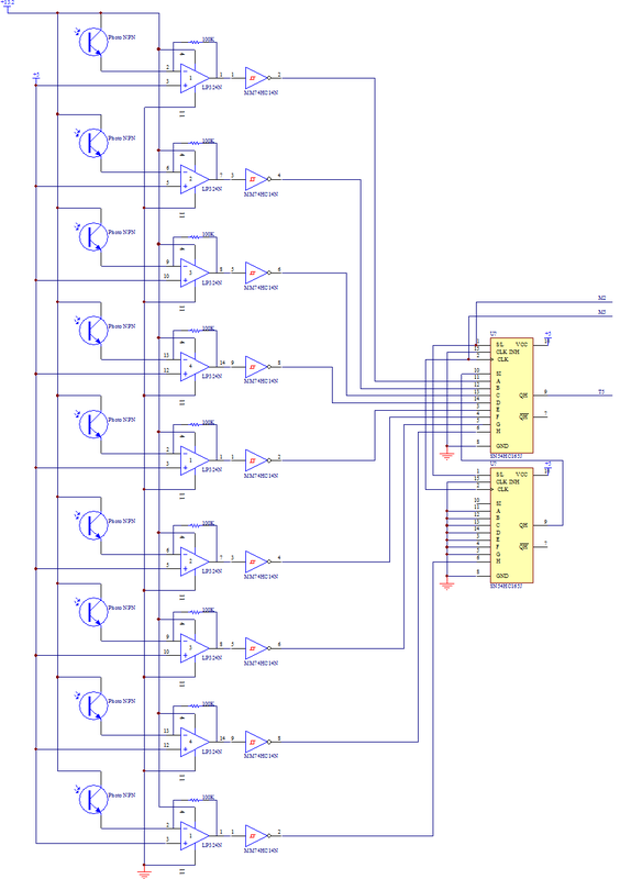
Input Shift Register Circuit for Phototransistors
To detect user targeting, we used 9 phototransistors as input signals. The inputs are each amplified through an op-amp, passed through a Schmitt trigger, and translated into a digital signal. Using a cascading series of input shift registers, we use 3 lines from the C32 to interpret the inputs.
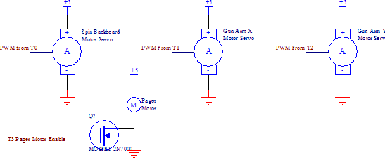
Drivers for Servos & Motors
The three servos for turning the backboard, adjusting the gun aim horizontally, and adjusting the gun aim vertically all connect to power, ground and a PWM signal from the T port of the microcontroller. The pager motor runs from a digital output of the microcontroller, switched with a 2N7000 MOSFET in high side drive.
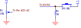
Potentiometer & Button Input Circuit
The analog voltage signal from the potentiometer is used to determine the desired position of the gameboard. It's vary ranges from approximately 5V to 0V. The button is used to drive a digital signal to the microcontroller. In software, both inputs are digitially filtered to limit the speed of response of the gameboard servo, and debouncing.
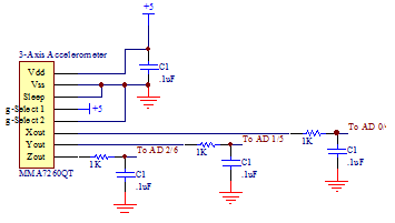
Accelerometer Circuit
An accelerometer is located in each controller, and is used to aim the laser, or to win the coin toss mode. The g-select pins set the sensitivity of the accelerometer to 1.5g, and the 3 outputs provide analog outputs between 0 and 3.3V, which are then sent through a low pass filter. The sleep line on the accelerometer must be tied to HIGH, NOT LOW.